Cable Management Best Practices: 2026 Enterprise Standards & Physical Layer Compliance
1. Executive Summary: The Critical Role of Physical Layer Geometry
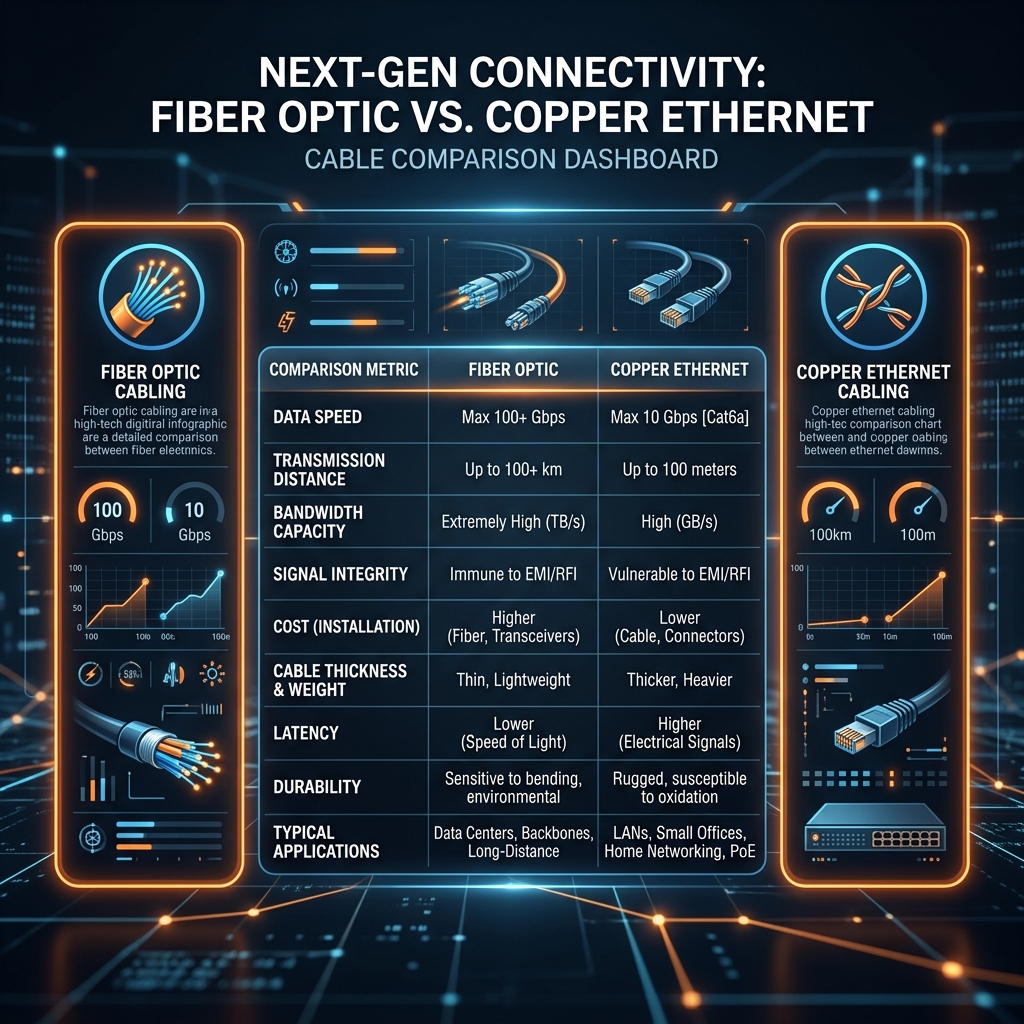
In the era of multi-gigabit enterprise networking, Wi-Fi 7 wireless backhauls, and high-power Power over Ethernet (PoE++ 100W) distribution, physical cable management can no longer be treated as an aesthetic afterthought. The physical geometry, containment pathways, and mechanical fastening of copper and fiber optic cabling directly govern the electrical and optical performance of the entire network infrastructure.
Improper cable dressing, excessive pinching, tight bend radii, and chaotic bundling introduce severe physical layer impairments. These micro-degradations manifest as alien crosstalk (ANEXT), structural return loss, magnetic core saturation, and thermal accumulation—ultimately leading to silent data corruption, CRC switch port errors, and premature hardware failure.
This comprehensive architectural guide establishes the definitive 2026 engineering standards for enterprise cable management. Network directors, infrastructure architects, and lead engineers will explore the rigorous physical layer mechanics required to guarantee 100% compliance with British Standards BS EN 50174, ISO/IEC 14763-2, and TIA-568.0-E across commercial and industrial facilities.
```
+------------------------+-----------------------------------+-----------------------------------+
| Management Parameter | Legacy Practice (Pre-2020) | 2026 Enterprise Standard |
+------------------------+-----------------------------------+-----------------------------------+
| Fastening Mechanism | Nylon Plastic Zip Ties | Wide Hook-and-Loop Velcro Straps |
| Containment Pathway | Enclosed Metallic Conduit | Open-Mesh Wire Basket Trays |
| Max PoE Bundle Size | Unrestricted / Box Fill | Maximum 24 Cables per Bundle |
| Cat6A Bend Radius | 1.0 inch (Aggressive Bends) | Minimum 4x Outer Diameter (~1.5") |
| Fire Rating Compliance | PVC / Basic CMP Plenum | CPR Euroclass B2ca / Cca LSZH |
+------------------------+-----------------------------------+-----------------------------------+
```
2. British Standard BS EN 50174 & ISO/IEC 14763-2 Mechanics
Achieving absolute physical layer reliability requires adhering to international statutory cabling standards. British Standard BS EN 50174 (Information technology - Cabling installation) and ISO/IEC 14763-2 provide the mandatory regulatory framework for the specification, quality assurance, and physical installation of structured cabling within commercial real estate.
Pathway Fill Ratios & Capacity Planning
A primary cause of physical layer degradation is the overfilling of horizontal containment pathways. When cable trays, basket baskets, and trunking are packed beyond their engineered capacity, the cumulative weight of the upper cable layers exerts severe crushing forces on the cables at the bottom of the tray. This mechanical compression alters the precise geometric positioning of the twisted pairs within the cable sheath, degrading near-end crosstalk (NEXT) performance.
```
Pathway Fill Ratio (%) = (Sum of Cable Cross-Sectional Areas / Internal Tray Area) * 100
```
Under BS EN 50174 standards, horizontal containment pathways must be engineered to a maximum initial fill ratio of 40%. This conservative allocation reserves 60% of the physical tray volume for future tenant expansion, emergency redundant pulls, and vital convective airflow. Under no circumstances should the absolute ultimate fill ratio exceed 60% during the operational lifecycle of the building.
Metallic vs. Non-Metallic Containment Systems
The choice of containment material directly impacts the electromagnetic shielding integrity of the cabling plant. While non-metallic PVC trunking provides lightweight, cost-effective routing for benign residential environments, enterprise commercial deployments mandate the installation of continuous metallic containment systems.
Galvanized steel wire basket trays and perforated heavy-gauge steel ladder racks provide superior mechanical support, excellent thermal dissipation, and vital equipotential bonding. When properly grounded in accordance with BS EN 50310, metallic containment acts as a highly effective barrier against external electromagnetic interference (EMI), safeguarding high-frequency 10GBASE-T data transmissions from industrial transient voltage spikes.
3. Bend Radius Physics & Optical/Copper Insertion Loss
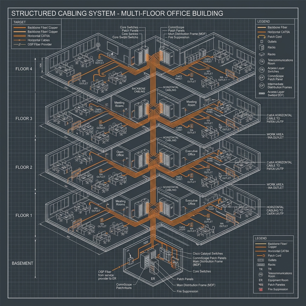
Every copper data cable and optical fiber possesses a minimum bend radius limit dictated by the physical properties of its internal conductors, dielectric insulation, and outer sheathing. Exceeding these mechanical limits through sharp 90-degree corners or tight loops introduces catastrophic signal attenuation.
```
+-------------------+-----------------------------------+-----------------------------------+
| Cable Category | Minimum Bend Radius (Operating) | Minimum Bend Radius (Pulling) |
+-------------------+-----------------------------------+-----------------------------------+
| Category 5e U/UTP | 4x Cable Outer Diameter (~0.9") | 8x Cable Outer Diameter (~1.8") |
| Category 6A F/UTP | 4x Cable Outer Diameter (~1.5") | 8x Cable Outer Diameter (~3.0") |
| Category 8 S/FTP | 4x Cable Outer Diameter (~1.7") | 8x Cable Outer Diameter (~3.4") |
| OM4 / OM5 Fiber | 10x Cable Outer Diameter | 20x Cable Outer Diameter |
+-------------------+-----------------------------------+-----------------------------------+
```
Copper Geometry & Structural Return Loss
Within a Category 6A or Category 8 copper cable, the four internal twisted pairs are precision-manufactured with varying twist rates and separated by a central internal spline (fluted separator). This internal geometry is meticulously calculated to cancel out electromagnetic coupling between adjacent pairs.
When a copper cable is bent beyond its minimum allowable radius (typically 4 times the outer diameter of the cable, or approximately 38mm for Cat6A), the internal pairs are forced out of their engineered geometric alignment. The conductors on the outside of the bend are stretched, while the conductors on the inside are compressed. This physical deformation creates an immediate impedance mismatch at the apex of the bend, causing signal energy to reflect back toward the transmitting switch port—a phenomenon measured as Structural Return Loss (SRL).
Optical Fiber Micro-Bending and Macro-Bending
Fiber optic cabling is exceptionally vulnerable to physical stress. Bending an OM4 multimode or OS2 singlemode glass core beyond its critical angle disrupts the principle of Total Internal Reflection (TIR).
4. Thermal Management & PoE++ Bundling Discipline
The widespread adoption of IEEE 802.3bt Type 4 Power over Ethernet (PoE++) has transformed data cabling into a high-power electrical distribution grid capable of delivering up to 100W of direct current per link. Pushing high current through tightly bundled copper conductors generates substantial resistance heat (I²R loss), making thermal management a paramount concern for 2026 infrastructure architects.
```
Heat Dissipation (Watts) = I² * R_loop
```
The Dangers of Nylon Zip Ties
For decades, nylon plastic zip ties were the standard fastening mechanism used by electrical contractors to secure data cables. However, in high-power PoE++ and multi-gigabit deployments, nylon zip ties represent a severe physical layer hazard.
Installers utilizing mechanical tensioning tools frequently over-tighten plastic zip ties, creating severe localized pinch points. This mechanical compression permanently deforms the soft copper conductors and crushes the internal dielectric insulation. Furthermore, as PoE++ current warms the cable bundle, the copper conductors expand against the rigid, unyielding plastic zip tie, exacerbating the structural compression and accelerating outer jacket degradation.
Velcro Hook-and-Loop Fastening Mandate
To ensure physical layer compliance and preserve internal cable geometry, 2026 enterprise standards strictly mandate the exclusive use of wide, soft hook-and-loop Velcro straps for all data cable dressing and bundling.
```
+------------------------+-----------------------------------+-----------------------------------+
| Fastening Attribute | Nylon Plastic Zip Ties | Hook-and-Loop Velcro Straps |
+------------------------+-----------------------------------+-----------------------------------+
| Mechanical Pressure | High / Localized Pinching | Distributed / Soft Cushioning |
| Thermal Expansion | Rigid / Restricts Expansion | Flexible / Accommodates Swelling |
| MACs (Moves/Changes) | Destructive / Requires Cutting | Reusable / Zero Tooling Required |
| Geometry Preservation | Poor / Crushes Internal Spline | Excellent / Maintains Twist Rates |
+------------------------+-----------------------------------+-----------------------------------+
```
Velcro straps distribute mechanical support evenly across the entire surface area of the cable sheath, completely eliminating localized pinch points. When adding, removing, or modifying cables within a bundle, technicians can effortlessly unfasten and re-secure Velcro straps without requiring sharp cutting tools that risk accidentally severing adjacent live data runs.
Open-Mesh Wire Basket Trays vs. Enclosed Conduit
When dozens of PoE++ cables are tightly packed inside enclosed metallic or PVC conduit, the internal cables situated at the core of the bundle are completely deprived of convective airflow. Heat generated by the copper conductors becomes trapped, causing internal bundle temperatures to exceed 70°C (158°F). This thermal baking increases electrical insertion loss and forces network switches to consume additional power to push signals through the higher resistance.
Enterprise architectures must prioritize the installation of open-mesh galvanized steel wire basket trays. The open grid design allows ambient air to circulate freely around the cable bundles, facilitating rapid thermal dissipation and maintaining cable operating temperatures within certified margins. Where cable bundles must traverse enclosed fire-rated spaces, architects must derate the maximum bundle size to no more than 24 cables per group.
5. Electromagnetic Interference (EMI) & Alien Crosstalk Mitigation
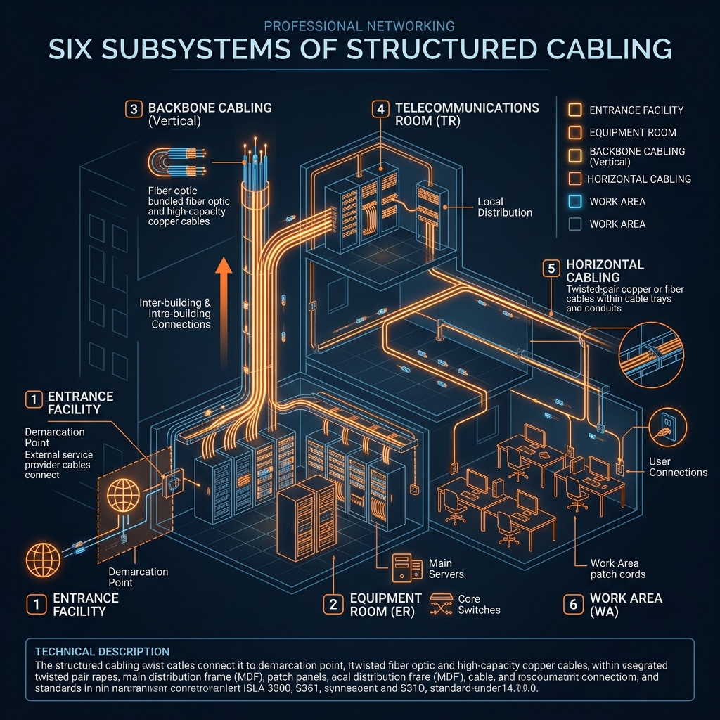
In modern commercial and industrial facilities, data cabling shares ceiling plenums and riser shafts with high-voltage electrical distribution feeders, variable frequency drives (VFDs), and heavy HVAC machinery. Protecting low-voltage data signals from external electromagnetic interference (EMI) and radio frequency interference (RFI) is critical for maintaining error-free multi-gigabit forwarding.
Alien Crosstalk (ANEXT) Mechanics
While near-end crosstalk (NEXT) refers to signal coupling between adjacent twisted pairs within the *same* cable sheath, Alien Crosstalk (ANEXT) is the destructive electromagnetic coupling that occurs between adjacent cables within a tightly bound bundle. Because adjacent cables possess identical internal twist rates, their electromagnetic fields easily synchronize and interfere with one another.
ANEXT is the single most significant limiting factor for 10GBASE-T data transmission over Category 6A cabling. Unlike internal NEXT, which can be partially mitigated by sophisticated Digital Signal Processing (DSP) cancellation algorithms embedded within switch silicon ASICs, ANEXT is completely unpredictable and cannot be canceled by active networking hardware.
Shielded F/UTP vs. Unshielded U/UTP Cabling
To eliminate ANEXT in high-density enterprise environments, infrastructure architects must evaluate the shielding mechanics of the cabling plant:
Grounding and Bonding Discipline (BS EN 50310)
Deploying shielded F/UTP cabling requires implementing a rigorous, end-to-end grounding and bonding architecture in strict accordance with British Standard BS EN 50310. The aluminum foil shield within each cable must be properly terminated to shielded keystone jacks at both the patch panel and the work area outlet.
```
+----------------------------------------+-----------------------------------+
| Electrical Source | Minimum Separation Distance |
+----------------------------------------+-----------------------------------+
| Unscreened Power Lines (<35 kVA) | 200 mm (8.0 inches) |
| Unscreened Power Lines (>35 kVA) | 500 mm (20.0 inches) |
| Screened Power Lines (Armored/SWA) | 50 mm (2.0 inches) |
| Fluorescent / LED Driver Luminaires | 130 mm (5.1 inches) |
+----------------------------------------+-----------------------------------+
```
The shielded patch panels must be bonded directly to the Telecommunications Grounding Busbar (TGB) utilizing heavy-gauge copper grounding wire. If a shielded cabling system is improperly grounded, the foil shield acts as an ungrounded antenna, actively absorbing ambient electromagnetic noise and dumping it directly into the differential data pairs, causing massive packet loss.
Furthermore, BS EN 50174 mandates strict physical separation distances between data containment pathways and high-voltage electrical conduits. Where data cables must cross power conduits, the crossing must occur at an exact 90-degree right angle to minimize the physical area of electromagnetic exposure.
6. Telecom Room (TR) & Patch Panel Architecture
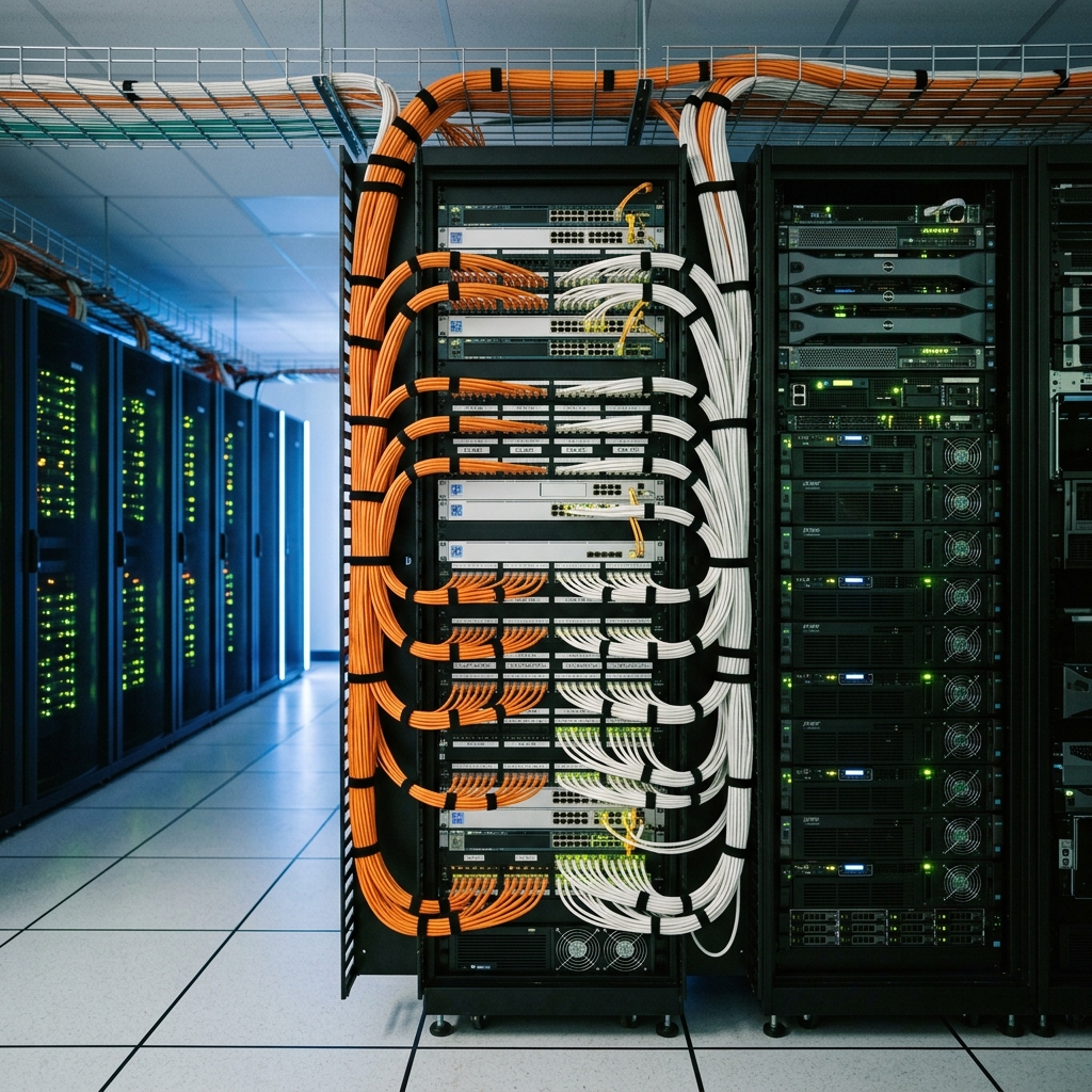
The Telecommunications Room (TR) is the central nerve center of the enterprise physical layer. Chaotic, unmanaged patch cords, congested rack frames, and undocumented cross-connects severely impair ongoing operational maintenance, increase mean time to repair (MTTR) during network outages, and restrict vital rack airflow.
```
+------------------------+-----------------------------------+-----------------------------------+
| Rack Architecture | Conventional Flat Patch Panels | High-Density Angled Patch Panels |
+------------------------+-----------------------------------+-----------------------------------+
| Horizontal Managers | Mandatory (Requires 1U/2U Space) | Eliminated (Zero Horizontal Space)|
| Patch Cord Routing | Direct Pull / Sharp Rack Bends | Sweeping Curve into Vertical Trays|
| Rack Density (42U) | 50% Active Ports / 50% Management | 85%+ Active Ports / High Density |
| Airflow Efficiency | Restricted by Cable Congestion | Unrestricted / Clean Equipment Bay|
+------------------------+-----------------------------------+-----------------------------------+
```
High-Density Angled Patch Panels
Conventional flat patch panels require dedicated horizontal cable managers (typically 1U or 2U in height) mounted directly above and below each panel to support the patch cords. In a standard 42U equipment rack, these horizontal managers consume up to 50% of the available rack space, severely limiting equipment density.
Enterprise architectures utilize high-density angled patch panels. The physical V-shaped angle of the panel naturally directs patch cords into the vertical side managers of the rack frame, completely eliminating the need for horizontal cable managers. This innovative geometry allows architects to double the active port density within a single 42U rack while maintaining pristine, sweeping patch cord bend radii.
Zero-U Vertical Managers & Horizontal Lacer Bars
To support the massive volume of patch cords entering the equipment bays, enterprise racks must be equipped with wide, high-capacity zero-U vertical cable managers featuring smooth internal routing fingers and hinged protective doors.
At the rear of the patch panels, heavy horizontal lacer bars (strain relief bars) must be securely installed. Every incoming horizontal data cable must be dressed and secured to the lacer bar utilizing Velcro straps before terminating into the keystone jack. This mechanical strain relief ensures that the physical weight of the cable run does not exert pulling tension on the delicate IDC (Insulation Displacement Connector) punch-down blocks, preventing micro-disconnections over time.
TIA-606-C Color-Coding and Labeling Administration
Absolute physical layer reliability requires implementing a standardized, intuitive labeling and color-coding administration system in accordance with TIA-606-C standards. Every patch cord, keystone jack, patch panel port, and containment pathway must be clearly identified utilizing permanent, machine-printed thermal transfer labels.
```
+-------------------+-----------------------------------+-----------------------------------+
| Service Type | TIA-606-C Color Standard | Enterprise Application |
+-------------------+-----------------------------------+-----------------------------------+
| Demarcation / WAN | Orange | Incoming Fiber / Leased Lines |
| Network Backbone | White | Main Cross-Connect / Core Switches|
| Common Data | Blue | Standard Desktop / Workstation LAN|
| VoIP Telephony | Silver / Grey | Dedicated Voice over IP Networks |
| Physical Security | Yellow | CCTV Cameras / Access Control |
| Life Safety / IoT | Green | Fire Alarms / Building Automation |
+-------------------+-----------------------------------+-----------------------------------+
```
By establishing a rigid color-coding hierarchy, network engineers can instantly identify the specific service type and security classification of any active patch cord within a congested telecom room. This visual intelligence prevents technicians from accidentally disconnecting critical life-safety or surveillance circuits during routine workstation maintenance.
7. Comprehensive Expert Frequently Asked Questions
What are the mandatory physical separation distances between Category 6A data cables and high-voltage electrical conduits under BS EN 50174?
Under British Standard BS EN 50174, unscreened data cables must maintain a minimum physical separation distance of 200mm (8 inches) from unscreened electrical power lines under 35 kVA, and 500mm (20 inches) from power lines exceeding 35 kVA. If the electrical cables are enclosed within grounded metallic conduit or armored steel wire (SWA), the separation distance can be safely reduced to 50mm (2 inches). Where crossings are unavoidable, they must execute at an exact 90-degree right angle to minimize electromagnetic coupling.
Why does bending a Category 6A copper cable beyond its minimum bend radius cause Structural Return Loss (SRL)?
Category 6A cables are manufactured with precise internal pair twist rates separated by a central internal fluted spline. When the cable is bent tighter than its minimum bend radius (4 times the outer diameter, or ~38mm), the internal pairs are forced out of their engineered geometric alignment. This physical deformation alters the characteristic impedance at the bend apex, causing high-frequency signal energy to reflect back toward the transmitting switch port—a severe impairment known as Structural Return Loss (SRL).
What is the difference between CPR Euroclass B2ca, Cca, and Dca fire ratings for commercial network cabling?
The Construction Products Regulation (CPR) establishes uniform fire performance standards for cabling installed within European and UK buildings.
How do wide hook-and-loop Velcro straps prevent alien crosstalk (ANEXT) compared to nylon plastic zip ties?
Nylon plastic zip ties are rigid and narrow. When tightened utilizing mechanical tensioning tools, they create severe localized pinch points that crush the internal cable jacket and force adjacent cables into intimate physical contact, dramatically increasing Alien Crosstalk (ANEXT). Wide hook-and-loop Velcro straps distribute mechanical support evenly across the cable sheath, providing a soft cushioning buffer that preserves internal pair geometry and maintains the necessary physical separation between adjacent cables to keep ANEXT within certified limits.
Why is DC Loop Resistance Unbalance testing critical when certifying cable plants for 100W PoE++ deployments?
Within a 4-pair PoE++ cable, direct current must flow perfectly evenly between the two conductors of each twisted pair. If improper termination techniques or damaged keystone jacks introduce a minor resistance unbalance between the two wires, current will flow asymmetrically. This uneven electrical flow creates a differential magnetic field inside the switch port isolation transformer, causing magnetic core saturation that distorts multi-gigabit data waveforms and results in massive CRC packet loss.