PoE Power Budget Planning: 2026 Enterprise Architecture & Thermal Management Guide
1. Executive Summary: The 100W PoE++ Imperative
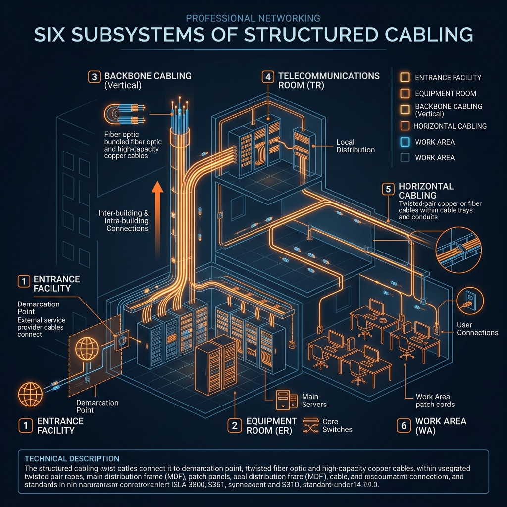
The rapid convergence of smart building IoT, Wi-Fi 7 access points, and pan-tilt-zoom (PTZ) 4K surveillance cameras has fundamentally transformed enterprise data cabling infrastructure. Modern commercial facilities no longer treat Ethernet cabling merely as a data transmission medium; it has become the primary low-voltage electrical distribution backbone.
Executing a flawless Power over Ethernet (PoE) deployment requires transitioning from basic spreadsheet estimations to rigorous thermal and electrical engineering. Failure to accurately calculate power budgets, cable resistance drop, and bundle heat dissipation inevitably leads to catastrophic switch power supply failures and silent data corruption.
This comprehensive architectural guide establishes the definitive engineering standards for deploying IEEE 802.3af, 802.3at, and 802.3bt (PoE++) infrastructure across commercial real estate. Network directors will learn how to balance power allocations, mitigate thermal rise in enclosed cable trays, and guarantee 100% compliance with British Standards BS EN 50174 and TIA/EIA-568-D.
2. IEEE PoE Standards & Electrical Mechanics
Understanding the underlying electrical mechanics of the IEEE 802.3 standards is the foundational prerequisite for designing enterprise power budgets. Each standard dictates specific voltage ranges, current limitations, and active wire-pair utilization to ensure safe power delivery over standard twisted-pair copper cabling.
```
+---------------+------------------+------------------+------------------+-------------------+
| IEEE Standard | Common Name | Switch Port Pwr | Powered Dev Pwr | Supported Pairs |
+---------------+------------------+------------------+------------------+-------------------+
| 802.3af | PoE (Type 1) | 15.4 W | 12.95 W | 2-Pair |
| 802.3at | PoE+ (Type 2) | 30.0 W | 25.5 W | 2-Pair |
| 802.3bt | PoE++ (Type 3) | 60.0 W | 51.0 W | 4-Pair |
| 802.3bt | PoE++ (Type 4) | 90.0 W / 100 W | 71.3 W | 4-Pair |
+---------------+------------------+------------------+------------------+-------------------+
```
Type 1 & Type 2: 802.3af and 802.3at Mechanics
Legacy IEEE 802.3af (Type 1) delivers up to 15.4W at the PSE (Power Sourcing Equipment) switch port, ensuring approximately 12.95W reaches the PD (Powered Device) after accounting for inherent cable resistance loss over a 100-meter run. This power tier remains perfectly suited for standard static VoIP telephones, basic proximity access control card readers, and fixed 1080p indoor dome security cameras.
As enterprise demands increased, the IEEE 802.3at (PoE+) standard was ratified to deliver 30W at the PSE switch port, providing a minimum guaranteed 25.5W at the edge device. Utilizing two pairs of copper conductors, PoE+ provides the necessary electrical headroom to power dual-band Wi-Fi 6 access points, advanced biometric security turnstiles, and outdoor heated camera enclosures.
Type 3 & Type 4: The 802.3bt (PoE++) Revolution
The ratification of IEEE 802.3bt fundamentally altered enterprise network architecture by introducing Type 3 (60W) and Type 4 (90W/100W) power delivery capabilities. Unlike legacy standards that energized only two pairs of copper wire, 802.3bt utilizes all four pairs simultaneously (4PPoE) to distribute electrical current across the entire cable cross-section.
By dividing the direct current across all eight copper conductors, Type 4 PoE++ significantly reduces overall loop resistance while doubling active power delivery capabilities. This enables network switches to directly power high-output commercial LED smart lighting grids, digital signage displays, 4K multi-sensor PTZ tracking cameras, and high-performance Wi-Fi 7 enterprise access points.
3. Calculating the Enterprise Power Budget
Designing a resilient enterprise switch stack requires calculating the exact cumulative power draw of all connected edge devices under maximum load conditions. Network architects must avoid the common pitfall of relying on average operational wattage ratings published on standard vendor marketing specification sheets.
```
Total Switch Power Budget = Sum(PD Max Wattage) / (Switch Efficiency * Cable Loss Factor)
```
Derating Switch Power Supplies
Enterprise network switches equipped with dual redundant power supplies (e.g., 1100W or 1600W hot-swappable modular units) rarely dedicate 100% of their nameplate wattage capacity exclusively to PoE forwarding. Internal switch silicon ASICs, high-speed backplane forwarding planes, and cooling fan assemblies consume between 150W and 300W of baseline internal operational power.
Consequently, a 48-port PoE+ switch equipped with a 1000W power supply may only offer an active PoE power budget of 740W for edge device allocation. Attempting to deploy forty 25W PoE+ devices on this switch will immediately exceed the available 740W budget, forcing the switch power management controller to actively shed load by shutting down lower-priority switch ports.
LLDP Power Negotiation & Dynamic Allocation
To prevent accidental power supply overload, modern enterprise switches utilize Link Layer Discovery Protocol (LLDP-MED) to dynamically negotiate power allocations with connected edge devices. When a powered device initially connects to a switch port, the PSE allocates a safe default power class rating (e.g., Class 3 at 15.4W) during the physical hardware classification handshake.
Once the operating system boots, the edge device transmits granular LLDP packets specifying its exact operational power requirements down to the tenth of a watt. The switch management plane continuously monitors these LLDP requests, dynamically reclaiming unused power capacity from idle switch ports and redistributing it to high-demand active ports in real time.
4. Cable Resistance & Thermal Management Engineering
Pushing 100W of continuous direct current through tightly bundled copper cabling generates significant resistance heat (I²R loss) within enclosed ceiling plenums and riser shafts. Managing this thermal rise is the single most critical engineering challenge in high-power PoE++ infrastructure design.
```
Heat Dissipation (Watts) = I² * R_loop
```
Conductor Gauge: 23 AWG vs. 24 AWG
The physical diameter of the copper conductor directly dictates its electrical resistance and thermal dissipation capabilities. Legacy Category 5e cabling typically utilizes thinner 24 AWG conductors, which present higher loop resistance and generate substantial internal heat when subjected to continuous 60W or 90W PoE loads.
Enterprise PoE++ deployments mandate the installation of Category 6A cabling featuring thicker 23 AWG solid copper conductors. The increased cross-sectional surface area of 23 AWG copper dramatically reduces electrical insertion loss, minimizes voltage drop over long 100-meter runs, and keeps cable operating temperatures safely within certified parameters.
Cable Bundling & Containment Tray Discipline
When dozens of PoE++ cables are tightly bound together using plastic zip ties inside enclosed metallic conduit, the internal cables within the center of the bundle are completely insulated from ambient airflow. This thermal entrapment can cause temperatures within the center of the bundle to exceed 70°C (158°F), resulting in severe physical degradation of the outer cable sheathing.
```
+-------------------+--------------------+--------------------+
| Bundle Size | Cat5e (24 AWG) Max | Cat6A (23 AWG) Max |
+-------------------+--------------------+--------------------+
| 1 - 19 Cables | 60 Watts | 100 Watts |
| 20 - 37 Cables | 45 Watts | 90 Watts |
| 38 - 74 Cables | 30 Watts | 71 Watts |
| 75+ Cables | Not Recommended | 60 Watts |
+-------------------+--------------------+--------------------+
```
To comply with British Standard BS EN 50174 and prevent dangerous thermal accumulation, network installers must enforce strict cable bundle size limitations and containment discipline. High-power PoE bundles should be limited to a maximum of 24 cables per group, loosely secured utilizing wide hook-and-loop Velcro straps, and deployed in open-mesh wire basket trays to maximize ambient convective cooling.
5. Physical Layer Testing & Verification Protocols
Deploying a mission-critical PoE++ network requires comprehensive physical layer certification testing prior to energizing switch ports. Standard wire-map continuity testers are completely incapable of identifying subtle resistance imbalances that cause severe magnetic saturation within switch isolation transformers.
Direct Current (DC) Loop Resistance Unbalance Testing
Within a standard 4-pair Ethernet cable, electrical current must be divided perfectly equally between the two conductors of each twisted pair. If improper termination techniques, severe cable kinking, or low-quality RJ45 keystone jacks introduce a minor resistance unbalance between the two wires, the electrical current will flow unevenly across the pair.
This uneven current distribution generates a differential magnetic field within the PSE switch port Ethernet isolation transformer, causing severe core saturation, extreme jitter, and complete data packet loss. Professional cable certification requires utilizing advanced diagnostic tools, such as the Fluke Networks DSX-8000 Cable Analyzer, to perform rigorous DC Loop Resistance Unbalance testing across every installed link.
Time-Domain Reflectometry (TDR) & Return Loss Diagnostics
When verifying high-power PoE pathways supporting multi-gigabit data transmission (2.5G/5G/10GBASE-T), certification engineers must measure return loss reflections along the entire cable run. Minor impedance mismatches caused by excessive untwisting of wire pairs at termination points create signal echoes that collide with incoming data packets.
Utilizing Time-Domain Reflectometry (TDR), advanced cable analyzers transmit high-frequency electrical pulses down the wire to pinpoint the exact physical distance to any impedance anomalies. Identifying and remediating these micro-faults ensures that the cabling infrastructure can simultaneously support 100W PoE++ power delivery and flawless 10Gbps data forwarding without experiencing CRC interface errors.
6. Power Backup & UPS Sizing Strategies
Transitioning building systems and physical security hardware to a centralized PoE infrastructure concentrates all electrical dependencies directly into the main enterprise switch room. Designing a robust Uninterruptible Power Supply (UPS) architecture is paramount for maintaining life-safety and security operations during a municipal grid power failure.
```
Required UPS VA Rating = (Total Active PoE Load + Switch Baseline Power) * 1.25 Safety Margin
```
Calculating Runtime Reserves for Emergency Systems
When sizing an enterprise UPS system, network architects must calculate the total cumulative wattage draw of all active PoE switches and apply a minimum 25% safety derating margin to account for power factor inefficiencies. Furthermore, facilities supporting IP-based emergency voice evacuation systems or mandatory CCTV recording archives must guarantee specific minimum battery runtime reserves.
For standard commercial offices, a 30-minute battery runtime reserve provides sufficient operational bridging while automated diesel backup generators execute their startup and transfer synchronization sequences. However, high-risk industrial facilities and healthcare environments mandate deploying extended-run external battery cabinets capable of sustaining full 100W PoE++ loads for up to 4 hours of continuous operation.
Managed Power Shedding & Port Priority Configuration
During an extended municipal power outage where diesel generator backup is unavailable, enterprise switches must be configured to execute automated, intelligent power shedding to preserve remaining UPS battery reserves. Network administrators achieve this by assigning explicit power priority classifications (High, Medium, Low) to every active switch port within the management dashboard.
When the centralized UPS management card signals that battery capacity has dropped below 50%, the core switches automatically terminate power delivery to Low-priority ports—such as employee desktop VoIP phones and decorative architectural PoE lighting grids. This aggressive load shedding immediately reduces overall battery draw, extending the remaining runtime reserve for High-priority life-safety systems, perimeter access control doors, and critical surveillance cameras.

7. Comprehensive Expert Frequently Asked Questions
What is the exact difference between IEEE 802.3at (PoE+) and IEEE 802.3bt (PoE++)?
IEEE 8-2.3at (PoE+) delivers a maximum of 30W at the switch port utilizing two pairs of copper conductors, providing 25.5W at the edge device. IEEE 802.3bt (PoE++) utilizes all four pairs of copper conductors simultaneously (4PPoE) to deliver up to 60W (Type 3) or 100W (Type 4) at the switch port, enabling support for high-draw devices like Wi-Fi 7 access points and smart LED lighting grids.
Why is 23 AWG Category 6A cabling mandatory for high-power PoE++ enterprise installations?
Category 6A cabling utilizes thicker 23 AWG solid copper conductors, which possess a larger cross-sectional surface area than legacy 24 AWG Cat5e cables. This increased copper volume significantly reduces electrical loop resistance (I²R loss), minimizing internal heat generation within enclosed cable trays and preventing destructive thermal degradation of the outer cable sheathing.
How does DC Loop Resistance Unbalance cause data packet loss in PoE switches?
If poor termination practices or damaged keystone jacks create unequal resistance between the two wires of a twisted pair, direct current will flow unevenly across the conductors. This asymmetrical current creates a differential magnetic field inside the switch port isolation transformer, causing magnetic core saturation that distorts high-frequency data waveforms and results in CRC packet drops.
What is Link Layer Discovery Protocol (LLDP-MED) and how does it optimize switch power budgets?
LLDP-MED is an advanced data link layer protocol that allows powered devices to dynamically negotiate their precise operational power requirements with the switch management plane. Instead of reserving static, worst-case wattage blocks (e.g., reserving 30W for a device that only uses 18W), the switch dynamically allocates exact wattage, allowing administrators to safely connect more devices to a single switch power supply.
What are the maximum recommended cable bundle sizes for 90W PoE++ installations under BS EN 50174?
To prevent dangerous heat accumulation in the center of cable bundles, British Standard BS EN 50174 recommends limiting 90W PoE++ Category 6A cable bundles to a maximum of 24 cables per group. These bundles must be loosely secured using wide Velcro straps rather than tight plastic nylon zip ties, and should be deployed in open-mesh wire containment trays to ensure adequate convective airflow.