Fiber Optic Upgrade Guide
Executive Summary
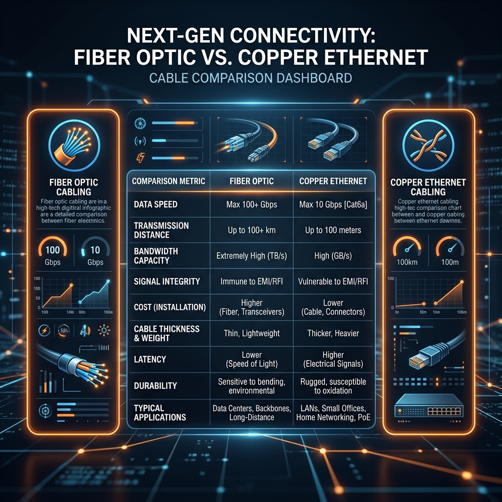
As enterprise bandwidth demands exceed the physical limitations of copper cabling, upgrading campus and vertical backbone infrastructure to fiber optics becomes imperative. This guide outlines the engineering principles, fiber selection criteria, and professional splicing standards required to deploy high-speed optical networks capable of supporting 40Gbps, 100Gbps, and beyond.
Core Architecture & Technical Specifications
Commercial fiber deployments are categorized into multimode and single-mode optical architectures. For internal building backbones up to 400 meters, laser-optimized OM4 multimode fiber (50/125µm) provides a highly cost-effective solution for multi-gigabit transmission utilizing VCSEL transceivers.
For sprawling campus environments or inter-building links exceeding 500 meters, OS2 single-mode fiber (9/125µm) is mandatory. Single-mode infrastructure eliminates modal dispersion, enabling virtually unlimited bandwidth potential over immense distances using high-precision laser optics operating at 1310nm or 1550nm wavelengths.
Installation Standards & Best Practices
Verification & Testing Protocols
Optical link certification requires Tier 1 and Tier 2 testing regimens. Tier 1 testing utilizes Optical Loss Test Sets (OLTS) to measure total link end-to-end attenuation and verify polarity. Tier 2 testing employs Optical Time Domain Reflectometers (OTDR) to characterize the entire fiber link, verifying the precise loss of every individual splice, connector, and macro-bend along the run.
Frequently Asked Questions
What is the difference between OM4 multimode and OS2 single-mode fiber?
OM4 multimode features a larger 50µm core that allows multiple light modes to propagate simultaneously, ideal for shorter, cost-effective LED/VCSEL links. OS2 single-mode features a tiny 9µm core that allows only a single beam of light to pass, eliminating modal dispersion and enabling ultra-high-speed transmission across vast distances.
Why is fusion splicing preferred over mechanical splicing?
Mechanical splicing aligns fiber ends within a physical sleeve using matching gel, resulting in higher insertion loss (0.2dB to 0.5dB) and potential long-term degradation from gel dry-out. Fusion splicing uses an electric arc to permanently weld the glass cores together, producing an incredibly robust connection with near-zero signal loss.
How do dirty optical connectors impact network performance?
A single microscopic speck of dust on a fiber optic end-face can block or scatter the light beam, causing massive insertion loss and severe optical return loss (reflectance). In high-power laser systems, trapped contamination can even burn and permanently pit the polished glass surface.
Related Forensic Intelligence
Author: Gary Pearce - Security & Data Specialist. 20+ years engineering forensic-grade surveillance and networking solutions across the North East UK.