Enterprise Wi-Fi Deployment: 2026 RF Engineering & High-Density Architecture
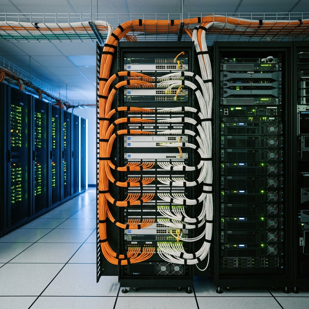
1. Executive Summary: The Wi-Fi 7 Paradigm Shift
The ratification of IEEE 802.11be (Wi-Fi 7) has fundamentally transformed enterprise mobility architecture. Modern commercial facilities, corporate campuses, and industrial logistics centers no longer view wireless networking as a secondary convenience layer; it has become the primary mission-critical access medium for high-bandwidth cloud applications, real-time IoT sensor grids, and ultra-low-latency autonomous robotics.
Deploying a resilient, high-density enterprise Wi-Fi network requires transitioning from basic coverage estimations to empirical Radio Frequency (RF) engineering. Failure to accurately model structural attenuation, calculate Signal-to-Noise Ratio (SNR) margins, and mitigate co-channel interference (CCI) inevitably leads to severe packet jitter, dropped VoIP roaming handoffs, and catastrophic throughput collapse during peak operational loads.
This comprehensive architectural guide establishes the definitive 2026 engineering standards for enterprise Wi-Fi deployment. Network directors, senior RF engineers, and infrastructure architects will explore the rigorous physical and MAC layer mechanics required to guarantee 100% wireless availability, seamless roaming, and ironclad WPA3 security across complex commercial floorplates.
```
+------------------------+-----------------------------------+-----------------------------------+
| Architectural Metric | Legacy Wi-Fi 6 (802.11ax) | 2026 Enterprise Wi-Fi 7 (802.11be)|
+------------------------+-----------------------------------+-----------------------------------+
| Maximum Channel Width | 160 MHz | 320 MHz (Ultra-Wide 6GHz Band) |
| Peak Modulation Density| 1024-QAM | 4096-QAM (4K-QAM) |
| Multi-Band Capability | Single-Link Roaming | Multi-Link Operation (MLO) |
| Wired Uplink Mandate | 1 Gbps (1000BASE-T) | Dual 10G / 2.5GBASE-T PoE++ |
| Enterprise Encryption | WPA2 / WPA3-Personal Transition | WPA3-Enterprise 192-bit CNSA Suite|
+------------------------+-----------------------------------+-----------------------------------+
```
2. RF Propagation Physics across 2.4GHz, 5GHz, and 6GHz Bands
Designing a high-performance wireless network requires a deep mastery of electromagnetic wave propagation physics. The enterprise spectrum is divided into three distinct unlicensed frequency bands, each possessing unique physical characteristics governing range, penetration, and spectral capacity.
Free Space Path Loss (FSPL) & Frequency Attenuation
As an electromagnetic wave radiates outward from an access point antenna, its power density diminishes inversely with the square of the distance from the source—a fundamental principle defined as Free Space Path Loss (FSPL). Crucially, FSPL is directly proportional to the transmission frequency; higher frequency signals experience significantly greater atmospheric absorption and rapid signal degradation over distance.
```
FSPL (dB) = 20 * log10(Distance_km) + 20 * log10(Frequency_MHz) + 32.44
```
Consequently, a 6 GHz Wi-Fi 7 signal attenuates much faster through open air than a legacy 2.4 GHz signal. To achieve parity in received signal strength (RSSI) at the edge of a cell, 6 GHz access points require higher transmit power allocations or significantly denser physical deployment grids compared to lower-frequency bands.
Structural Wall Attenuation Factors
When electromagnetic waves encounter physical building materials, they experience a combination of reflection, absorption, refraction, and scattering. The exact decibel (dB) loss introduced by an interior partition depends heavily on the material's density, moisture content, and internal metallic reinforcement.
```
+----------------------------------------+-------------------+-------------------+
| Building Material | 5 GHz Attenuation | 6 GHz Attenuation |
+----------------------------------------+-------------------+-------------------+
| Standard Drywall / Plasterboard (12mm) | 3 dB (50% Loss) | 4 dB (60% Loss) |
| Interior Glass Window (Un-tinted) | 2 dB | 3 dB |
| Brick Wall (Standard 100mm) | 10 dB | 13 dB |
| Reinforced Concrete Riser (200mm) | 20 dB (99% Loss) | 25 dB |
| Metallic Elevator Shaft / Foil Backing | 30+ dB (Complete) | 30+ dB (Complete) |
+----------------------------------------+-------------------+-------------------+
```
Architects must account for these structural attenuation factors during the predictive modeling phase. Passing through a single standard drywall partition cuts the effective signal power in half (-3 dB). Attempting to provide coverage into an executive boardroom through a reinforced concrete shear wall (-20 dB) will result in complete signal loss, necessitating the installation of a dedicated access point directly within the room.
The 6 GHz Band & 320 MHz Ultra-Wide Channels
The regulatory opening of the 6 GHz frequency band represents the most significant expansion of Wi-Fi spectrum in history, delivering up to 1,200 MHz of pristine, uncongested greenfield spectrum. Unlike the legacy 2.4 GHz band (which contains only three non-overlapping 20 MHz channels) or the DFS-constrained 5 GHz band, the 6 GHz band easily accommodates up to seven non-overlapping 160 MHz channels or three massive 320 MHz ultra-wide channels.
Deploying 320 MHz channel widths enables multi-gigabit over-the-air data rates exceeding 5 Gbps per client device. However, doubling the channel width increases the thermal noise floor by 3 dB, requiring client devices to maintain a significantly higher Signal-to-Noise Ratio (SNR) to successfully demodulate the incoming data stream.
3. Advanced Modulation & Multi-Link Operation (MLO) Mechanics
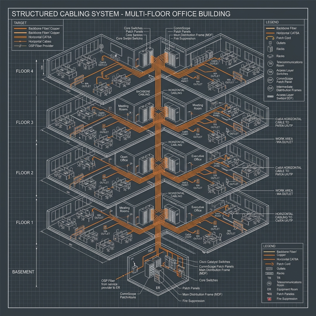
Wi-Fi 7 introduces revolutionary physical (PHY) and Medium Access Control (MAC) layer enhancements designed to maximize spectral efficiency and provide deterministic, ultra-low-latency forwarding for mission-critical enterprise applications.
4096-QAM (4K-QAM) Density & SNR Thresholds
Quadrature Amplitude Modulation (QAM) manipulates both the phase and amplitude of a carrier wave to encode multiple bits of data into a single transmitted symbol. While Wi-Fi 6 peaked at 1024-QAM (10 bits per symbol), Wi-Fi 7 introduces 4096-QAM, packing 12 bits of data into every individual symbol—representing an instant 20% increase in raw data throughput.
```
+-------------------+--------------------+--------------------+
| Modulation Tier | Bits per Symbol | Minimum Required SNR|
+-------------------+--------------------+--------------------+
| 64-QAM (Wi-Fi 4) | 6 bits | ~22 dB |
| 256-QAM (Wi-Fi 5) | 8 bits | ~29 dB |
| 1024-QAM (Wi-Fi 6)| 10 bits | ~35 dB |
| 4096-QAM (Wi-Fi 7)| 12 bits | ~41 dB (Pristine) |
+-------------------+--------------------+--------------------+
```
Achieving 4096-QAM modulation requires an exceptionally clean RF environment with an SNR exceeding 41 dB. If ambient electromagnetic noise or co-channel interference degrades the SNR below this threshold, the access point and client device will dynamically down-shift their modulation coding scheme (MCS) to a lower, more robust tier (e.g., 1024-QAM or 256-QAM), sacrificing throughput to maintain link stability.
Multi-Link Operation (MLO) Architecture
In legacy Wi-Fi architectures, a dual-band client device could only establish a single active connection to an access point on either the 2.4 GHz, 5 GHz, or 6 GHz band at any given time. If the active channel experienced a sudden spike in radar interference or congestion, the client was forced to execute a disruptive, high-latency roaming transition to another band.
Wi-Fi 7 eliminates this bottleneck through Multi-Link Operation (MLO). MLO enables a client device to simultaneously bond multiple frequency bands (e.g., 5 GHz and 6 GHz) into a single aggregated virtual link at the MAC layer.
```
+-------------------------------------------------------------------+
| Wi-Fi 7 Multi-Link Operation (MLO) MAC Layer Aggregation |
+-------------------------------------------------------------------+
| +-----------------------+ +-------------------------------+ |
| | 5 GHz PHY Transceiver | <-> | Simultaneous Packet Forwarding| |
| +-----------------------+ | Frame Duplication / Balancing | |
| +-----------------------+ | Ultra-Low Latency Engine | |
| | 6 GHz PHY Transceiver | <-> | | |
| +-----------------------+ +-------------------------------+ |
+-------------------------------------------------------------------+
```
MLO operates in two distinct operational modes:
Preamble Puncturing for Interference Mitigation
In legacy 802.11ac/ax networks, if an incumbent narrow-band signal (such as an automated weather radar or legacy Bluetooth transmitter) occupied a 20 MHz slice within a bonded 160 MHz channel, the access point was forced to collapse its entire transmission width down to a basic 20 MHz channel to avoid interfering with the incumbent signal.
Wi-Fi 7 resolves this inefficiency through Preamble Puncturing. The access point dynamically "slices out" the specific 20 MHz sub-channel containing the interference while maintaining simultaneous transmission across the remaining 140 MHz of clean spectrum. This sophisticated spectral carving ensures high-bandwidth forwarding remains uncompromised despite localized narrow-band interference.
4. Empirical Site Surveying & Spectrum Analysis
Deploying a carrier-grade enterprise Wi-Fi network requires replacing theoretical spreadsheet estimates with rigorous, empirical site surveying diagnostics. Relying solely on predictive software models without validating real-world structural attenuation inevitably results in severe coverage gaps and overlapping interference zones.
```
+------------------------+-----------------------------------+-----------------------------------+
| Survey Methodology | Predictive Simulation Only | Empirical Ekahau Sidekick 2 Audit |
+------------------------+-----------------------------------+-----------------------------------+
| Wall Attenuation | Estimated from Software Library | Empirically Measured via Laser/RF |
| Spectrum Analysis | Ignored / Assumes Clean Air | Active Dual-Band Hardware Sweep |
| Noise Floor Accuracy | Static Default (-92 dBm) | Real-time Measured (-98 to -85 dBm)|
| CCI Identification | Theoretical Calculation | Live Beacon Decoding & Mapping |
+------------------------+-----------------------------------+-----------------------------------+
```
Ekahau Sidekick 2 Hardware Diagnostics
Professional enterprise site surveys mandate the utilization of calibrated diagnostic hardware, specifically the Ekahau Sidekick 2. Unlike standard USB Wi-Fi adapters that scan channels sequentially using slow, uncalibrated consumer chipsets, the Sidekick 2 features four enterprise-grade tri-band Wi-Fi radios paired with a lightning-fast 50 sweeps-per-second diagnostic spectrum analyzer.
During an active continuous site survey, the field engineer walks the facility floorplate while the Sidekick 2 continuously captures high-resolution RF propagation metrics across the 2.4 GHz, 5 GHz, and 6 GHz bands simultaneously. This empirical data provides absolute precision regarding active Signal-to-Noise Ratios, precise roaming boundaries, and actual physical data rates achieved throughout the building.
Co-Channel Interference (CCI) vs. Adjacent Channel Interference (ACI)
When designing high-density enterprise channel plans, RF engineers must meticulously avoid introducing self-induced interference:
5. High-Density Access Point Architecture & Placement Strategy
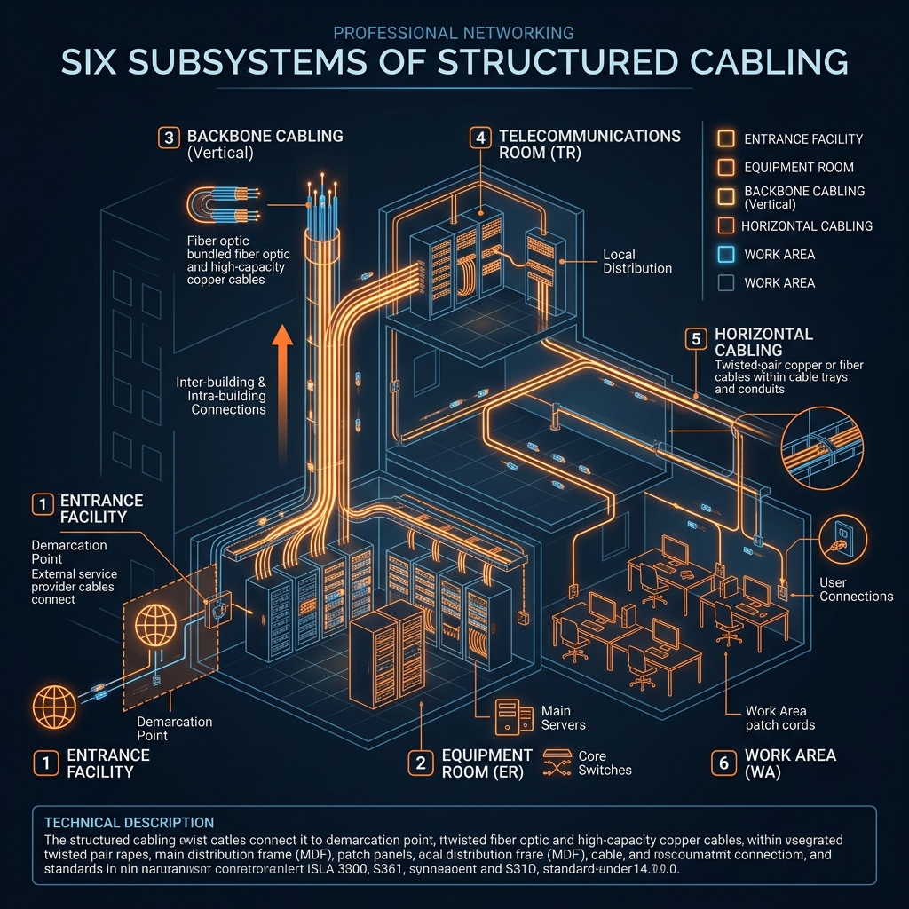
High-density enterprise environments—such as corporate auditoriums, university lecture halls, and open-plan trading floors—present extreme capacity challenges. Designing for high density requires shifting the architectural priority from maximizing physical *coverage* to maximizing spectral *re-use*.
```
+------------------------+-----------------------------------+-----------------------------------+
| Architectural Approach | Standard Office Deployment | High-Density Auditorium Design |
+------------------------+-----------------------------------+-----------------------------------+
| Access Point Density | 1 AP per 2,500 sq ft | 1 AP per 750 sq ft (Micro-Cells) |
| Antenna Selection | Internal Omnidirectional | External High-Gain Directional |
| Transmit Power (EIRP) | High (18 - 22 dBm) | Minimum (8 - 11 dBm) |
| Minimum Basic Rate | 12 Mbps | 24 Mbps (Aggressive Pruning) |
+------------------------+-----------------------------------+-----------------------------------+
```
Micro-Cell Engineering & Transmit Power Tuning
In a standard office environment, access points are typically deployed with higher transmit power settings to provide broad coverage cells. However, in high-density environments where hundreds of client devices are packed into a single room, broad coverage cells result in catastrophic Co-Channel Interference as multiple APs hear one another across the open space.
Architects must engineer high-density spaces utilizing Micro-Cell Architecture. Access points are deployed in a dense grid with their transmit power (EIRP) dialed down to minimum operational levels (typically 8 to 11 dBm). This intentional cell shrinkage creates small, isolated pockets of RF coverage, allowing engineers to re-use identical frequency channels on opposite sides of the room without introducing CCI.
Directional vs. Omnidirectional Antennas
Standard enterprise access points feature internal omnidirectional antennas that radiate RF energy equally in all directions (resembling an expanding doughnut). While ideal for standard ceiling heights (2.5m to 3.5m), omnidirectional APs mounted on high open ceilings (6m to 12m) waste massive amounts of RF energy radiating outward into the upper ceiling plenum while failing to deliver adequate signal strength to client devices on the floor.
High-ceiling commercial environments mandate the deployment of external high-gain directional patch antennas. Directional antennas focus the RF energy downward into a precise, controlled conical beam (e.g., 30-degree or 60-degree beamwidths). This concentrated beam cuts through ambient thermal noise, delivers exceptional SNR directly to the floorplate, and prevents RF bleed into adjacent deployment zones.
Dynamic Radio Resource Management (RRM) & RRM Tuning
Modern enterprise wireless controllers utilize advanced AI-driven Radio Resource Management (RRM) algorithms to dynamically monitor the ambient RF environment. RRM continuously analyzes neighbor AP beacon reports, client roaming trajectories, and external radar interference spikes, automatically adjusting AP transmit power and channel assignments in real time.
However, network architects must establish strict boundary governors within the RRM configuration profile. Administrators must clamp the maximum allowable AP transmit power to prevent runaway power escalations during temporary environmental anomalies. Furthermore, minimum basic management rates must be aggressively pruned (e.g., disabling all legacy 802.11b/g data rates below 24 Mbps) to force distant, sticky client devices to roam to closer access points, preserving valuable airtime for high-speed clients.
6. Enterprise Security & Wired Infrastructure Prerequisites
A world-class wireless mobility architecture is entirely dependent on the structural integrity, power delivery capabilities, and cryptographic security of the underlying wired network infrastructure.
```
+------------------------+-----------------------------------+-----------------------------------+
| Infrastructure Layer | Legacy Standard | 2026 Enterprise Mandate |
+------------------------+-----------------------------------+-----------------------------------+
| Switch Port Speed | 1000BASE-T (1 Gbps) | 2.5G / 5G / 10GBASE-T (mGig) |
| Power over Ethernet | IEEE 802.3at PoE+ (30W) | IEEE 802.3bt PoE++ (60W / 100W) |
| Cabling Category | Category 5e / Category 6 | Category 6A F/UTP Shielded |
| Authentication | WPA2-PSK / Pre-Shared Key | 802.1X RADIUS / EAP-TLS |
| Cryptographic Suite | AES-CCMP 128-bit | GCMP-256 / 192-bit CNSA Suite |
+------------------------+-----------------------------------+-----------------------------------+
```
WPA3-Enterprise 192-bit CNSA Suite Encryption
Securing enterprise intellectual property and maintaining strict compliance with ISO 27001 mandates replacing vulnerable pre-shared key (PSK) architectures with robust WPA3-Enterprise cryptographic suites. WPA3 completely eliminates offline dictionary brute-force attacks by replacing the legacy 4-way handshake with Simultaneous Authentication of Equals (SAE).
For high-security corporate environments, financial institutions, and government facilities, network architects must implement the WPA3-Enterprise 192-bit Commercial National Security Algorithm (CNSA) suite. This elite cryptographic tier utilizes 256-bit Galois/Counter Mode Protocol (GCMP-256) for robust data confidentiality and 384-bit Elliptic Curve Diffie-Hellman (ECDH) exchange for unbreakable forward secrecy.
802.1X RADIUS Authentication & EAP-TLS
Enterprise access control mandates implementing port-based 802.1X authentication backed by a centralized RADIUS/TACACS+ identity provider (e.g., Cisco ISE or Aruba ClearPass). To eliminate the vulnerability of compromised employee passwords, organizations must deploy Extensible Authentication Protocol - Transport Layer Security (EAP-TLS).
EAP-TLS requires installing a cryptographic client certificate directly onto every managed enterprise device via an automated Mobile Device Management (MDM) platform. When a client attempts to associate with an access point, mutual certificate authentication occurs before any IP traffic is permitted onto the network, guaranteeing that unauthorized personal rogue devices are completely isolated from the corporate LAN.
Multi-Gigabit (mGig) & PoE++ 802.3bt Switch Port Budgeting
Enterprise Wi-Fi 7 access points equipped with 4x4:4 tri-band transceivers easily exceed over-the-air data forwarding rates of 5 Gbps. Connecting these high-performance APs to legacy 1 Gbps (1000BASE-T) switch ports creates an immediate, catastrophic wired bottleneck at the switch interface.
```
+-------------------------------------------------------------------+
| Enterprise Wi-Fi 7 Access Point Wired Uplink Architecture |
+-------------------------------------------------------------------+
| +---------------------------+ +---------------------------+ |
| | mGig Switch Port 1 (PoE++)| --> | Primary 10GBASE-T Uplink | |
| +---------------------------+ | (Hitless PoE++ Failover) | |
| +---------------------------+ | | |
| | mGig Switch Port 2 (PoE++)| --> | Secondary 10GBASE-T Uplink| |
| +---------------------------+ +---------------------------+ |
+-------------------------------------------------------------------+
```
Furthermore, powering three active high-output RF transceivers, internal ASICs, and dedicated Bluetooth/IoT scanning radios requires substantial electrical current. Wi-Fi 7 access points demand IEEE 802.3bt Type 3 (60W) or Type 4 (90W) Power over Ethernet (PoE++) delivery.
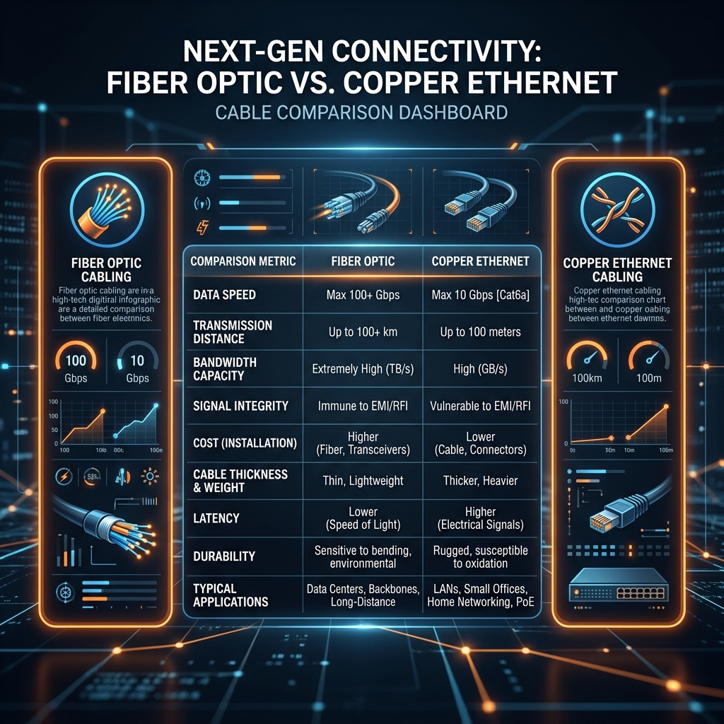
Enterprise infrastructure architectures must deploy multi-gigabit (2.5G/5G/10GBASE-T) access switches equipped with robust modular power supplies capable of sustaining continuous 90W PoE++ output across every active port. To ensure absolute physical layer reliability, Category 6A F/UTP shielded cabling must be installed to support the massive data rates while preventing destructive thermal accumulation within enclosed ceiling cable trays.
7. Comprehensive Expert Frequently Asked Questions
How do Ekahau Wi-Fi heatmapping surveys eliminate co-channel interference in enterprise deployments?
Professional Ekahau site surveys utilize calibrated Sidekick 2 diagnostic spectrum analyzers to measure active RF propagation across commercial floorplates. This empirical analysis allows network engineers to optimize access point placement, adjust channel widths, and eliminate co-channel interference (CCI) before deploying high-density Wi-Fi 6E or Wi-Fi 7 access points.
What is the exact difference between Co-Channel Interference (CCI) and Adjacent Channel Interference (ACI)?
Co-Channel Interference (CCI) occurs when adjacent access points operate on the exact same frequency channel. Because Wi-Fi is a half-duplex medium, all devices on the channel must wait for the airwaves to clear before transmitting, forcing devices into prolonged contention wait states that destroy throughput. Adjacent Channel Interference (ACI) occurs when access points operate on overlapping frequency channels (e.g., channels 1 and 2 in 2.4GHz). Sideband radiation bleeds directly into the adjacent channel, raising the noise floor and corrupting active data frames, making ACI exceptionally destructive.
How does Multi-Link Operation (MLO) improve roaming and latency in Wi-Fi 7 enterprise networks?
Multi-Link Operation (MLO) enables a Wi-Fi 7 client device to simultaneously bond multiple frequency bands (e.g., 5GHz and 6GHz) into a single aggregated virtual link at the MAC layer. In Simultaneous Transmit and Receive (STR) mode, it doubles aggregate throughput. In Ultra-Low Latency mode, the AP transmits identical redundant packets across both bands simultaneously; whichever packet arrives first is processed while the duplicate is instantly discarded, guaranteeing sub-millisecond jitter for real-time voice and automation traffic.
Why is Category 6A F/UTP shielded cabling mandatory for Wi-Fi 7 access point deployments?
Wi-Fi 7 access points equipped with 4x4:4 tri-band transceivers demand multi-gigabit (2.5G/10GBASE-T) backhaul speeds and IEEE 802.3bt PoE++ (60W/90W) power delivery. Category 6A F/UTP shielded cabling utilizes thicker 23 AWG solid copper conductors encased in an overall aluminum foil shield. The thicker copper minimizes resistance heat generation under 90W loads, while the foil shield completely eliminates Alien Crosstalk (ANEXT) between adjacent cables, ensuring error-free 10Gbps data forwarding.
What is WPA3-Enterprise 192-bit CNSA Suite encryption and when is it required?
WPA3-Enterprise 192-bit Commercial National Security Algorithm (CNSA) suite is an elite cryptographic tier designed for high-security corporate, financial, and government environments. It utilizes 256-bit Galois/Counter Mode Protocol (GCMP-256) for robust data confidentiality and 384-bit Elliptic Curve Diffie-Hellman (ECDH) exchange for unbreakable forward secrecy, completely eliminating brute-force vulnerabilities and meeting strict ISO 27001 compliance mandates.